MXA-5000 AIS Receiver

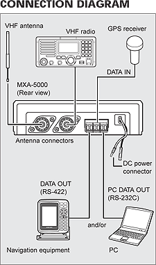
MXA5000 connection diagramDual channel receive capability

The MXA-5000 receives both Ch. 87B (161.975MHz) and Ch. 88B (162.025MHz) simultaneously. This dual channel receive makes the MXA-5000 more flexible for obtaining AIS information from AIS transponders that operate on only one channel. In addition, the MXA-5000 also receives both Class A and Class B AIS data.

Dual mode data output

The MXA-5000 has two data output. One is RS-422 for connection with equipment such as marine radar or GPS chart plotter. Those equipments which accept the VDM sentence format will show the AIS data on the display. The second is RS-232C for PC connection. When using with AIS plotter software*, the MXA-5000 allows you to monitor other vessel traffic on your PC.
*Not supplied from Icom.

Built-in antenna splitter to share one antenna

The MXA-5000 can be installed between a VHF antenna and a VHF radio. While receiving a VHF radio signal*, the MXA-5000 receives AIS data. When you transmit from the connected VHF radio, the Tx signal bypasses the MXA-5000 to protect the internal circuit.
*Insertion loss : 3.5dB (approx.)

GPS data multiplex

When connected a GPS receiver to the MXA-5000, GPS position information such as RMC, GGA, GNS and GLL formats can be multiplexed with AIS data (VDM format) and simplifies wiring.
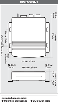
MXA5000 dimensionsCompact size and light weight body

The MXA-5000 is only 132(W)×34(H)×155(D)* mm and weighs only 400g* for easy and flexible installation.
*Mounting bracket is not included.

What is AIS?

Icom's MXA-5000 AIS (Automatic Identification System) receiver will pick up real- time transmissions from vessels that use an AIS transporter. Such transponders are now required for SOLAS vessels by SOLAS regulations.

The AIS transponder sends accurate navigation information such as:

Product Features
General

Frequency coverage

Rx

Tx

(unit: MHz)
0.5– 29.9999 (continuous)

1.6– 2.9999, 4.0– 4.9999, 6.0– 6.9999

8.0– 8.9999, 12.0– 13.9999, 16.0– 17.9999

18.0– 19.9999, 22.0– 22.9999, 25.0– 27.5000

Type of emission

J3E (SSB), J2B (AFSK), F1B
(FSK), A1A (CW), H3E (AM*)

*Rx only

Number of channels 1355 (max.)
(160 programmable channels; 249 ITU SSB duplex; 72 ITU
SSB simplex; 662 ITU FSK duplex; 160 e-mail; 21 ITU
4MHz simplex; 31 ITU 8MHz simplex)
Antenna impedance 50Ω (SO-239)
Power supply requirement 13.6V DC ±15%

Max. current drain

(at 13.6V DC)

Tx (Max. power) 30A (typ.)

Rx (Max. audio) 3.0A

Operating temp. range
Guaranteed range

–30°C to +60°C; –22°F to +140°F

–20°C to +55°C; –4°F to +131°F

Frequency stability ±10 Hz (at –20°C to +55°C)

Dimensions

Main unit
Controller
Speaker

 
240×94×238.4mm; 9716×31116×938in
220×110×84.4mm; 82132×41132×3516in
110×110×84.4mm; 41132×41132×3516in

Weight
Main unit
Controller
Speaker

 
4.7kg; 10.36lb
570g; 1.26lb
370g; 0.81lb
Transmitter
Output power 150, 60, 20W PEP (Selectable)
Spurious emissions –62dB
Unwanted sideband 55dB
Carrier suppression 40dB
Microphone impedance 2.4kΩ
Receiver

Sensitivity (at 10dB S/N)

  J3E, A1A J2B, F1B H3E DSC (J2B)
0.5 – 1.5999 MHz 6.3µV 32µV 0.5µV
(at 1% error rate)
1.6 – 1.7999 MHz 0.89µV 0.89µV 6.3µV
1.8 – 3.9999 MHz 0.5µV 0.5µV 3.2µV
4.0 –29.9999 MHz  

Spurious response

rejection ratio

Tx/Rx (1.5-29.9999MHz) More than 70dB
DSC (Except 1st IF image) More than 50dB
DSC (1st IF image) More than 60dB
Audio output power 4.0W at 10% distortion with a 4Ω load
Audio output impedance: 4–8Ω
Clarity variable range ±150 Hz
GPS interface NMEA 0183 version 3.01
Product Accessories
  • AT-140 HF AUTOMATIC ANTENNA TUNER
    Matches the transceiver to a long wire antenna with little insertion loss. Cable connections are easy to install. AT-130 is also available.

    at140 automatic antenna tuner
  • OPC-566 POWER CABLE
    30' shielded control cable.
  • MN-100 ANTENNA MATCHER
    Match the transceiver to a dipole antenna. Covers all HF bands from 1.5 to 30MHz. Two 8m (26.2ft) antenna wires come attached.

    mn100 antenna matcher
  • MN-100L ANTENNA MATCHER
    Match the transceiver to a longwire antenna. Covers all HF bands from 1.5 to 30MHz. A 15m (49.2ft) antenna wire comes attached.

    mn100l antenna matcher
  • OPC-1147/N SHIELDED CONTROL CABLE
    10m (32.8ft) shielded control cable connects between AT-140 and transceiver. OPC-1147N is for use with AT-140 Version 36.

    opc1147n shielded control cable
  • HM-135 HAND MICROPHONE
    Water resistant, remote function mic. Same as supplied.
  • MB-75 FLUSH MOUNT KIT
    For mounting the controller or speaker to a panel.

    mb75 flush mount kit
  • SP-24 EXTERNAL SPEAKER 4×4-inch external speaker. Same as supplied. Input impedance: 4Ω. Max. input power: 7W.
  • AH-710 FOLDED DIPOLE ANTENNA
    Covers 1.9 to 30MHz band. Has an SO-239 connector and 30m (98.4ft) coaxial cable. Easy to assemble (non-kink construction).
  • RC-25 REMOTE CONTROLLER
    Remote controller head. Same as supplied. Only one control head can be used on the M802.
  • OPC-1106 SEPARATION CABLE
    5m (16.4ft) separation cable between controller and main unit. Same as supplied.